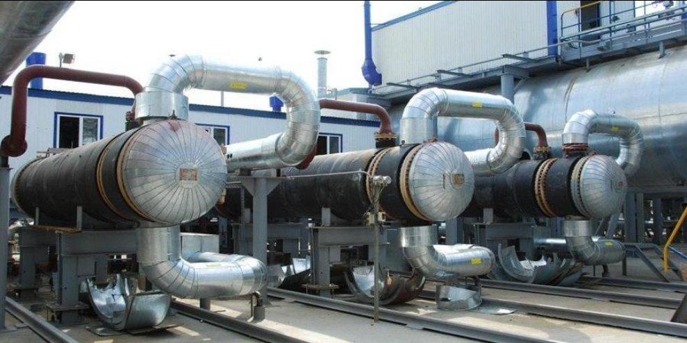
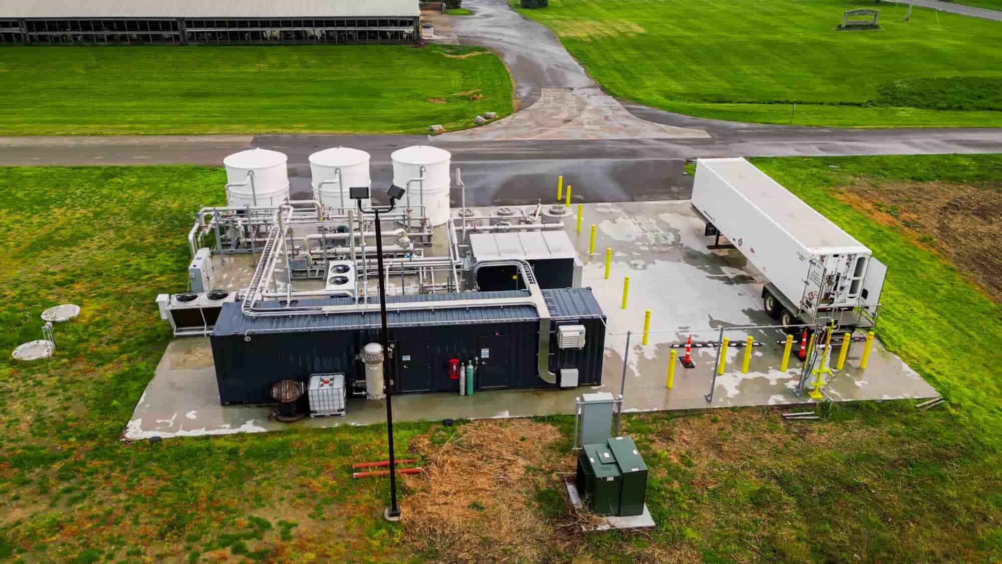
The Supplier shall design, manufacture, test, inspect and supply a complete Wellhead Heater, UN Model, suitable for heating crude oil and/or oil emulsion at the wellhead during transportation through field gathering systems.
The Wellhead Heater shall be supplied as a complete packaged unit including, as a minimum:
Heater vessel
Combustion chamber/furnace
Gas burner assembly
Gas separator
Ventilation system
Flue gas stack
Skid/base frame
Safety and control instrumentation
Temperature and pressure instruments
Fuel gas train
Shut-off and control valves
Safety relief devices
Local control panel
Required piping and fittings
Drain and sampling connections
Complete accessories required for safe and reliable operation
The heater shall be suitable for continuous outdoor operation at the oil/gas wellhead.
Equipment Description
Item | Specification |
|---|---|
Equipment | Wellhead Heater |
Model | UN-0.2M3 / UN Model |
Service | Crude Oil / Oil Emulsion Heating |
Installation | Wellhead / Field Gathering System |
Heating Type | Direct Heating |
Heating Medium | Combustion Products |
Fuel | Natural Gas / Associated Gas |
Installation | Skid Mounted |
Operation | Continuous |
Location | Outdoor |
Design | Horizontal Cylindrical Vessel |
Construction | Welded Steel Construction |
The heater shall transfer heat from the combustion chamber to the process fluid through the furnace/heating surface. The equipment shall be designed to provide uniform heating and prevent local overheating of the process fluid.
Design and Performance Requirements
Main Performance Data
Parameter | Required Specification |
|---|---|
Rated Thermal Capacity | 200 kW (0.2 Gcal/h) |
Oil Throughput | 50–100 t/day |
Maximum Operating Pressure | 1.6 MPa |
Maximum Thermal Efficiency | ≥80% |
Process Fluid | Crude Oil / Oil Emulsion |
Minimum Oil Inlet Temperature | +20°C |
Oil Outlet Temperature | +60 to +70°C |
Fuel Gas | Natural Gas / Associated Gas |
Fuel Gas Pressure at Burner | 30–70 kPa |
Fuel Gas Consumption | Approx. 15–25 Nm³/h |
Heater Wall Temperature | Approx. −20 to +70°C |
Installation | Skid Mounted |
The above values are based on published UN-0.2M3 reference data and should be finalized against the Purchaser's actual process conditions.
Process Connections
The following connection arrangement may be adopted for the UN-0.2M3 configuration:
Connection | Service | Qty. | Nominal Pressure | DN |
|---|---|---|---|---|
A1 | Oil Inlet | 1 | 1.6 MPa | DN100 |
B1 | Oil Outlet | 1 | 1.6 MPa | DN100 |
C1 | Safety Valve | 1 | 1.6 MPa | DN80 |
D1 | Drain | 1 | 1.6 MPa | DN50 |
E1 | Sampling Connection | 1 | 1.6 MPa | DN15 |
F1 | Gas Outlet to Flare/Candle | 1 | 0.15 MPa | DN15 |
G1 | Flue Gas Outlet | 1 | 0.01 MPa | DN250 |
These connection sizes correspond to the published UN-0.2M3 configuration. The Supplier shall verify all connection dimensions against the final approved GA drawing before manufacture.







Contact our engineering team to receive a customized proposal tailored to your industrial requirements.